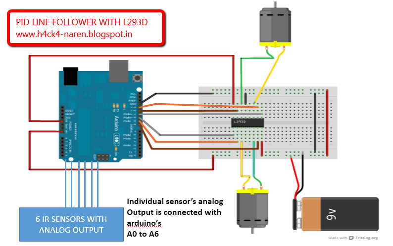
PID based line follower with L293D MOTOR DRIVER
1) 2 DC motors with
required wheels
This is a line follower
which implements PID to calculate its deviations from the line and act accordingly.
This gives the robot with high speed and less oscillations.
·
The proportional value
is approximately proportional to your robot’s position with respect to the
line. That is, if your robot is precisely centered on the line, we expect a
proportional value of exactly 0. If it is to the left of the line, the
proportional term will be a positive number, and to the right of the line, it
will be negative. This is computed from the result returned by read_line() simply
by subtracting 2000.
Diagram
Program
#include <QTRSensors.h>
#define Kp 0.5// experiment to determine this, start by something small that just makes your bot follow the line at a slow speed
#define Kd 2// experiment to determine this, slowly increase the speeds and adjust this value. ( Note: Kp < Kd)
#define rightMaxSpeed 150 // max speed of the robot
#define leftMaxSpeed 150 // max speed of the robot
#define rightBaseSpeed 150 // this is the speed at which the motors should spin when the robot is perfectly on the line
#define leftBaseSpeed 150 // this is the speed at which the motors should spin when the robot is perfectly on the line
#define NUM_SENSORS 6 // number of sensors used
#define TIMEOUT 2500 // waits for 2500 us for sensor outputs to go low
#define EMITTER_PIN 2 // emitter is controlled by digital pin 2
#define rightMotor2 4
#define rightMotorPWM 5
#define leftMotor2 11
#define leftMotorPWM 10
QTRSensorsRC qtrrc((unsigned char[]) {A0,A1,A2,A3,A4,A5} ,NUM_SENSORS, TIMEOUT, EMITTER_PIN); //analog sensor connected through analog pins A0 - A5
unsigned int sensorValues[NUM_SENSORS];
void setup()
{
Serial.begin(9600);
Serial.print("start");
pinMode(rightMotor2, OUTPUT);
pinMode(rightMotorPWM, OUTPUT);
pinMode(leftMotor2, OUTPUT);
pinMode(leftMotorPWM, OUTPUT);
digitalWrite(13,HIGH);
for (int i = 0; i < 300; i++) // calibrate for sometime by sliding the sensors across the line, or you may use auto-calibration instead
{
qtrrc.calibrate();
}
digitalWrite(13,LOW);
// comment out for serial printing
for (int i = 0; i < NUM_SENSORS; i++)
{
Serial.print(qtrrc.calibratedMinimumOn[i]);
Serial.print(' ');
}
Serial.println();
for (int i = 0; i < NUM_SENSORS; i++)
{
Serial.print(qtrrc.calibratedMaximumOn[i]);
Serial.print(' ');
}
Serial.println();
Serial.println();
}
int lastError = 0;
void loop()
{
unsigned int sensors[6];
int position = qtrrc.readLine(sensors); // get calibrated readings along with the line position, refer to the QTR Sensors Arduino Library for more details on line position.
int error = position - 2500;
Serial.println(position); //returns the current position of the robot to calculate the error.
int motorSpeed = Kp * error + Kd * (error - lastError);
lastError = error;
int rightMotorSpeed = rightBaseSpeed + motorSpeed;
int leftMotorSpeed = leftBaseSpeed - motorSpeed;
if (rightMotorSpeed > rightMaxSpeed )
rightMotorSpeed = rightMaxSpeed; // prevent the motor from going beyond max speed
if (leftMotorSpeed > leftMaxSpeed )
leftMotorSpeed = leftMaxSpeed; // prevent the motor from going beyond max speed
if (rightMotorSpeed < 0)
rightMotorSpeed = 0; // keep the motor speed positive
if (leftMotorSpeed < 0) leftMotorSpeed = 0; // keep the motor speed positive
{
analogWrite(rightMotorPWM, rightMotorSpeed);
digitalWrite(rightMotor2, LOW);
analogWrite(leftMotorPWM, leftMotorSpeed);
digitalWrite(leftMotor2, LOW);
}
}
void turn_left()
{
digitalWrite(5,HIGH);
digitalWrite(4,LOW);
}
void turn_right()
{
digitalWrite(10,LOW);
digitalWrite(11,HIGH);
}
Working
The Robot instantaneously checks the position of the robot and corrects accordingly. The robot is calibrated initially by exposing all the 6 six sensors to the black line so that the robot judges the dark and light bands with respective to its thickness.
The robot makes a reference position of the line and the robot and if the robot deviates it calculates the error and multiplies with a constant Kp and Kd and the result is fed to the speed of the motors.
PID calibration
Kp and Kd must be found out only by expt. Initially keep the Kp value as .5 and increase it slowly in order to make the robot follow the line. However after the robot starts to follow the line the deviations can be reduced to .1% error by slowly increasing the Kd value till the robot goes without oscillations .
No comments:
Post a Comment