Tuesday, 16 September 2014


Assembling of Line Follower

STEP 1:Place the motors on ur chassis and check the height of the BOT by fixing the wheels.
 
STEP 2: Place your arduino and H-BRIDGE on appropriate position for your connections
  
STEP 3: Place your sensors according to the problem statement

 STEP 4:your final bot . i will explain you the connections and the detailed configuration of the H-Bridge or Motor Driver IC (L293D)

Monday, 15 September 2014

One Sensor Line follower Arduino code
void setup()
{
pinMode(4,OUTPUT); //enable a
pinMode(8,OUTPUT); //enable b
pinMode(2,OUTPUT); //motor A
pinMode(3,OUTPUT);//motor A
pinMode(10,OUTPUT);//motor b
pinMode(9,OUTPUT);//MOTOR B
pinMode(5,INPUT);
pinMode(6,INPUT);
Serial.begin(9600);
}
void loop()
{
  digitalWrite(4,HIGH);
  digitalWrite(8,HIGH);
  int lsen,rsen;
  lsen=digitalRead(5);
  rsen=digitalRead(6);
  Serial.println(lsen);
  if((lsen==HIGH)&&(rsen==LOW))
  {
    right();
  }
  else if((rsen==HIGH)&&(lsen==LOW))
  {
    left();
  }
  else if((rsen==HIGH)&&(lsen==HIGH))
  {
    Stop();
  }
}
 
  void right()
  {
  digitalWrite(2,HIGH);
  digitalWrite(3,LOW);
  }
  void left()
  {
    digitalWrite(10,HIGH);
    digitalWrite(9,LOW);
  }
  void Stop()
  {
    digitalWrite(2,LOW);
    digitalWrite(3,LOW);
    digitalWrite(10,LOW);
    digitalWrite(9,LOW);
  }
DOWNLOAD THE ARDUINO CODE
https://docs.google.com/uc?export=download&id=0ByPWe4jRT6yGZEhGUDE0RFVtVFE


Sunday, 14 September 2014

Initialize your Arduino or Freeduino board

1) download the software from arduino.cc 
2)Install it . you will also have inbuilt drivers in it.
3)if you use freeduino use the following link 
https://docs.google.com/uc?export=download&id=0ByPWe4jRT6yGX3FZUHNHN0xKZUU
  4) plug in your arduino UNO or freeduino

5)check the com port connections from your device manager
            Right click Mycomputer--->manage--->device manager--->com ports & lpt's --->check uno driver com port no

6) open the arduino and go to tools then update the desired com port

7)select the desired board

8)open a example program from file and click upload .


Monday, 1 September 2014


                           ARDUINO BASIC AND INIT


Sorry for my delay in post i couldn't post" how to make line follower" on the time i promised .Before getting on how we can make a Line follower robot . I would like to share you few basics of the Arduino Board which you are goin to use in order  to program your micro-controller .
i would be pinning you a video in next post and it would explain on how you can install your arduino and how to code.

with the use of images Now i would like to explain you the Basic pins included on Arduino.

This is Arduino UNO where it is a small computer which is used to program the micro controller according to your needs . It can be used for your flexibility to design any projects from home automation to a perfect humanoid.
Now i wil explain you the various components of the Arduino board

EXTERNAL POWER SUPPLY
                             Ofcourse it provides supply to the board it can handle a max of 5V DC and when it is plugged in with the external power supply the board cannot be programmed and the existing program in the micro-controller will be executed.
moreover note that while using USB or EXT power supply the jumper on the board has to be changed accordingly.but now lately equipped board has auto configuration to detect the power.

USB PLUG
                          It is a serial connection made with your computer from the board with the computer .it is the interface which is used in order for the user to program . The user needs the interface to program namely ARDUINO or VISUAL STUDIO.
during the use of this your digital pin 0 and digital pin 1 will be in use by the USB and the pins cannot be used in the program .
Note:during the use of the serial print in the program the digital pin 0 and digital pin 1 shall be active to communicate with the computer COM port and the pin cannot be used.

DIGITAL PINS(0-13)
                     These pins are those which are used in programming . we define these pins as input or output .
if we declare these pins as input in the program then the micro controller expects the user to provide some input via these pins .SO the pins which are declared as INPUT must be given to some external sensors and after we receive the input then the input values can be processed using the programs.
PIN 0 AND PIN 1 are used for tx nd rx where they are used to make a serial communication with the external boards or devices like zig-bee etc...

DEFINING DIGITAL PINS IN PROGRAM FOR OUTPUT AND INPUT
          Usually the defining of the pins are made in the function called void setup();
Ex:
        void setup()
        {
             pinMode(3,INPUT);    //micro-controller expects a input value from pin 3
             pinMode(4,OUTPUT);//some output can be made with the pin 4
         }

NOTE:
                    Only digital signals can be sent in digital pins ie 0 volt or 5 volt
              Few pins in the board which is marked with symbol '~' is compatible with both digital and analog signals

Analog pins
           They are similar to digital pins but they can handle both digital as well as analog signals means we can vary voltage from 0v to 5v as well as use digital signals like 0v(low) or 5v(high).

Reset button
This button is not used to erase the program but however used to repeat the code from the first line of execution.

Reset pin on arudino
This pin is used in order to hardware reset the micro controller.
use of some resistor in between the 5v to reset pin is safe however when 5v is shorted with the reset pin even then the arduino is resetted.

STAY TUNED IN FOR MY NEXT POST ON INITIALISATION OF ARDUINO AND MAKIN A LINE FOLLOWER ROBOT

Saturday, 30 August 2014

I would like to post you my rates at which i can give you the spares for making a fine line follower..!!

chassis ---> Rs 100
IR sensors--->Rs 50 each
wheels      ---->Rs 14 each
Motor driver(L293D 1 Amp) --->Rs 100
Freeduino (Arduino compatable board)-->Rs 550
or
Arduino board --->Rs 1450
castor wheels--->Rs 10 each
DC motors(150 RPM) --->Rs 35 each
connecting wires (Male -Male or Male to Female)--->Rs 3.50 each wire
 courier charges--->based on the location

please contact @ narendranmontfort@gmail.com (or) maqunistatech@gmail.com

Stay tuned..ill post you how to make a Robot in 5 hrs

Friday, 29 August 2014

BASIC LINE FOLLOWER

*BASIC LINE FOLLOWER*

Final Top-View of the ROBOT done on montfort school ,Trichy on 18/09/14
This would be my first post and i would be teaching you how to make an "Perfect Line Follower Robot". Before getting into the technical description of the robot i would like to tell you how the robot is going to work and the ways you can build one and the materials required and where you can get those.

CONCEPT BEHIND LINE FOLLOWING


BLACK BODY EFFECT 


A black body allows all incident radiation to pass into it (no reflected energy) and internally absorbs all the incident radiation (no energy transmitted through the body). This is true for radiation of all wavelengths and for all angles of incidence. Hence the black body is a perfect absorber for all incident radiation.
So since fortunately darker bands absorb the light rays incident to it we are glad to make a sensor which would work by emitting a INFRARED RAY on the darker band and get a response back to judge a dark and the light band.

working of the robot


SINGLE SENSOR LINE FOLLOWER
Making a single sensor line follower is simple.The complexity of any line follower increases only when certain constraints are applied on the line on which it is gonna travel.The single sensor robot will take the algorithm as follows:

IF ROBOT PLACED ON THE LEFT SIDE OF THE BLACK LINE
             when sensor is not returning any potential difference the robot will turn left and when the sensor returns certain potential difference it would take a right turn.so this concept makes the robot follow the line.(PROGRAM SHALL E WRITTEN IN THE END OF THE POST)

IF ROOT PLACED ON THE RIGHT SIDE OF THE BLACK LINE
                 when sensor is not returning any potential difference the robot will turn right and when the sensor return certain potential difference it would take a left turn.

TWO SENSOR LINE FOLLOWER


THREE SENSOR ROBOT
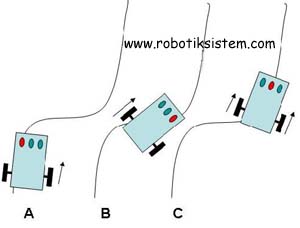
CASE 1:In a three sensor robot when the sensor 2 gets lowered then both the motor rotates in same direction in order to move forward.

CASE 2 :If the sensor 1 and sensor 2 returns a potential difference and sensor 3 doesn't return a potential difference then the Bot knows that it is in the left side of the line and it has to make a right turn.

NOTE: YOU CAN MAKE TWO POSSIBLE RIGHT TURN
FIRST WAY(REGULAR WAY)
                                                   ----> Stop the left motor and run the right motor in the direction in order to move forward.
SECOND WAY(FAST TURN)
                                                    ----->Instead of stopping the left motor run it in the Anti-clock wise direction and the right motor should be made to run in clockwise direction which makes the robot to stay still in the same place to have a small right turn and return to the previous  condition.

CASE 3: vice verse of case 2


MATERIALS  NEEDED TO MAKE A LINE FOLLOWER ROBOT

1) chassis
2)micro-controller for the computation
3)motor driver
4)batteries(High current preferred)
5)Two DC motors (RPM based on your requirements)
6)two wheels
7)IR sensors

                                                                 ------------->If you need any materials you can contact me @ narendranmontfort@gmail.com (or) https://www.facebook.com/narendranmontfort

**MAKING OF THE BOT SHALL BE POSTED IN MY NEXT POST....!!STAY TUNED..!!