Sunday, 25 January 2015

7. Serial communication from a computer or external device from an Arduino


PC to Arduino communication


This post describes on how a PC or any other wireless or wired device is going to send a message to a Arduino.This will explain a serial communication of a PC-Arduino & a Bluetooth-Arduino.


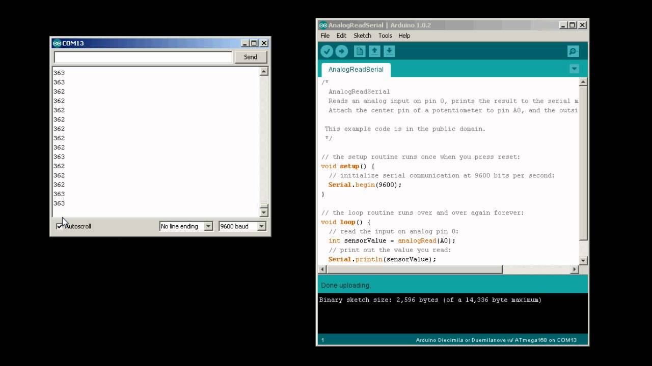
PC communication with a Arduino (Receiving serial data in Arduino)

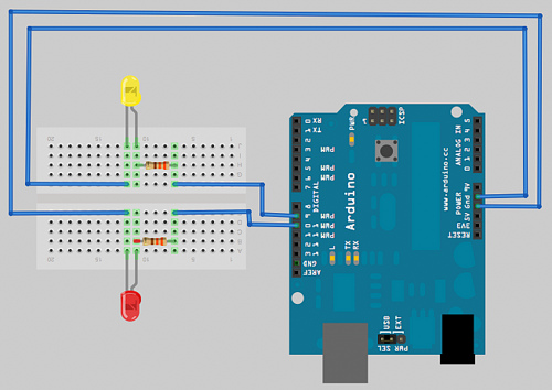
It is easy to receive 8-bit values ,because at Serial functions use 8 bit values.The following sketch receives a digit from the computer and blinks the LED based on the number which is pressed on the computer's keyboard.


int ledpin=13;
int blinkRate=0;

void setup()
{
  Serial.begin(9600);   //STARTS THE SERIAL COMMUNICATION
  pinMode(13,OUTPUT);   //ACTIVATES THE ONBOARD LED
}
void loop()
{
  if(Serial.available())
  {
    char ch=Serial.read();
    if(isDigit(ch))   //if it is a number bw 0 to 9 (checks the ascii value
    {
      blinkRate(ch-'0');  //entered number's ASCII value is converted to number
      blinkRate=blinkRate*100;
    }
    digitalWrite(13,HIGH);
    delay(blinkRate);
    digitalWrite(13,LOW);
    delay(blinkRate);
  }
}
      

Descriptoin

The above sketch gets an input from the serial communication and converts it to no of seconds to blink.

Step 1:  check whether Serial connection is avail by Serial.available().
Step 2:  Read the input .
Step 3: The read input will be in ASCII so convert it to numeric value.
Step 4: Convert the numeric value to seconds to notice the blink( if we dont convert then the blinks will be soo fast that it wont be visible with our eyes instead we need a high frame rate camera to see it).
Step 5:Use the blink sketch and blink the LED with respect to the BlinkRate of number.


Friday, 23 January 2015


6. Serial communications in Arduino

Introduction

Serial communication provides a easy way for Arduino to communicate with the computer and several other devices. The serial communication enables the computer to upload the programs to the computer as well as to send a data to computer.

Arduino IDE provides a serial monitor to display the data which is sent to the computer from the Arduino.


Data can be sent from the computer to the Arduino using the Text box avail on top of the serial monitor.
Baud Rate is selected using the drop down box on the bottom-right.You can use the drop down labelled "NO LINE ENDING"to automatically send a carriage return or a combination of a carriage return and a line at the end of each message sent when clicking the sent button by changing "No line ending"

Sending Information from your computer to your Arduino

Statement

You want to send text or data to be displayed on the PC using the Arduino IDE or the serial terminal program of your choice

Solution


void setup()
{
Serial.begin(9600); //begins a serial communication with the PC with the baud rate as 9600
}
void loop
{
int a;
Serial.print("The number is ");
Serial.print(a);
delay(600);
a=a+1;
}

OUTPUT

  The number is 0
  The number is 1
  The number is 2

// Number keeps on adding '1' and displays the output infinite times


Thursday, 22 January 2015

Data-types used on Arduino


Except in situations where maximum performance or memory efficiency is required,Variables declared using int will be suitable for numeric values if the values do not exceed the range and if you dont need to work with fractional values.Most of the official Arduino example code declares numeric variables as int.But sometimes you do not need to choose a type that specifically suite your application.

UNSIGNED AND SIGNED

Sometimes you need negative numbers and sometimes you don't, so numeric types come in two varities:signed and unsigned.unsigned values are always positive.
variables without keyword unsigned in front are signed so that they can represent negative and positive values.one reason to use unsigned values is when the range of signed values will not fit in the range of the variable .

BOOLEAN

They have two values namely : True or false. They are commonly used in situations in order to check the state of the switch to know whether it is ON or OFF.

Example for boolean

int Switch=10;
void setup()
{
  pinMode(Switch,INPUT);
  Serial.begin(9600);
}
void loop()
{
     boolean switchstat;
     int switch1=digitalRead(Switch);
     if(switch1==HIGH)
    {
         switchstat=true;
     }
     else
    {
        switchstat=false;
    }
   if(switchstat==true)
   {
              Serial.println("LIGHTS ON");
   }
   else
   {
              Serial.println("LIGHTS OFF");
    }
}


Next post on using FLOATING-POINT NUMBERS

Wednesday, 21 January 2015

Using a LDR with Arduino


To know about LDR check wikipedia


The sketch of the above schemetic is based on LED blinking code,but instead of using a fixed delay the rate is determined by the light sensitive sensor called LDR.

So now the following sketch will help you how to read the value of the LDR based on the sensitivity of light.

// Sketch to get the input from the LDR

int inputLDR=A0;
void setup()
{
  pinMode(inputLDR,INPUT);
 Serial.begin(9600);  // starts a serial connection with your computer to display the input of LDR with Baud rate of 9600
}
void loop()
{
   int a;    // to store the values which we received from the LDR
   a=analogRead(inputLDR); // Gets input from the LDR
   Serial.println(a);
}


Tuesday, 20 January 2015

Blinking an External LED with an Arduino


The above Schematic will guide you on how an External LED must be interfaced with an Arduino.
In the above case Two LED's red and yellow are connected.

you can use the same blink code which i have given in the previous  post.Instead of using the pin number as 13 you can use the pin 9 and 10;
Any range of resistors between 1K and 10k can be used .

Code to use the above Schematic for blink as well as fading the LED's

int redled=9;
int yellowled=10;
void Setup()
{
   pinMode(redled,OUTPUT);
   pinMode(yellowled,OUTPUT);
}
void loop()
{
// For the blink of both the led

digitalWrite(redled,HIGH);
digitalWrite(yellowled,HIGH);
delay(1000);
digitalWrite(redled,LOW);
digitalWrite(yellowled,LOW);
delay(1000);

// For fading the LED

for(int i=0;i<250;i++)
{
 analogWrite(redled,i);
 analogWrite(yellowled,i);
 }
for(int i=250;i<0;i--)
{
 analogWrite(redled,i);
 analogWrite(yellowled,i);
 }


}//end of loop


Comment either use of code to test the fading and blink


Monday, 19 January 2015

Blink code in Arduino ( Blink LED ON and OFF using Arduino)


/*
  Blink
  Turns on an LED on for one second, then off for one second, repeatedly.
 
  This example code is in the public domain.
 */
 
// Pin 13 has an LED connected on most Arduino boards.
// give it a name:
int led = 13;

// the setup routine runs once when you press reset:
void setup() {                
  // initialize the digital pin as an output.
  pinMode(led, OUTPUT);     
}

// the loop routine runs over and over again forever:
void loop() {
  digitalWrite(led, HIGH);   // turn the LED on (HIGH is the voltage level)
  delay(1000);               // wait for a second
  digitalWrite(led, LOW);    // turn the LED off by making the voltage LOW
  delay(1000);               // wait for a second
}


The following code is available by default in Arduino in File---->Examples---->basics----->blink

Working of the code

The pin 13 avail in the Arduino UNO has a On-board LED with a internal resistance with it .
so in order to activate the internal resistance the code " pinMode(led,OUTPUT) "(in void setup) is used.
The variable led is initialized with 13 and the pin 13 is said to be a output.
So the resistance of the on board LED is activated.


Now in void loop()  the code

digitalWrite(led, HIGH);   // turn the LED on (HIGH is the voltage level)
 
supplies 5v(ie Vcc) to the LED and hence it glows up..!! :D
now it has a delay(1000) which waits for one second and again it switches off the LED and waits for 1 sec.

This process repeats for ever in void loop()..!!


Getting Started with Arduino


The Arduino environment has been designed to be esy to use for beginners who have no software or electronics Xp's unlike me..!!With Arduino you can build objects that can respond to and/or control lights,sound,touch and movement..(What else do you probably need???)
So you can use Arduino to create your own musical instruments,Robots,light sculptures,games,interactive furniture and even interactive clothing .

Arduino is used in many educational programs around the world,particularly by designers and artists who want ot easily create prototypes but do not need a deep understanding of the technical detailes behind their creations.Because it is designed to be used by non-tech people the software includes plenty of example code to demonstrate how to use the Arduino board .

Arduino Software

Software programs called sketches are created on a computer using the Arduino IDE . The IDE enables you to write and edit code and convert this code into instructions that Arduino hardware understands.The IDE also transfers those instructions to the Arduino board.

Arduino Hardware Spec

 https://h4ckr-naren.blogspot.com/b/post-preview?token=g0a3BEsBAAA.hbmbliLvBIZwcMUU5Tb13A.wnqBlh_p3a-9M-dhxu5rRw&postId=7426553885776567980&type=POST