Monday, 2 February 2015

Arduino based House Security system


Making a Arduino based house security system is very easy.The above schematic shows how to work on PIR sensors,door sensors,vibration sensors and trigger a buzzer for emergency.The above model can be enhanced by adding GSM module to give a call to your mobile or check your security cameras on your mobile remotely.
Several advancement in house automation will be shared on blog as per the portions on Arduino based on difficulty level. 

Working

The working of the above connections with the Arduino is very simple. Arduino gets a input from the sensor as digital signal and triggers the alarm when the burglar system is active.
placement of various sensor must be the factor responsible for better enhancement of security. Door sensor must be placed on one side of the door and the magnet has to be fixed on the other closing end in such a way that the opening of the door must trigger the Arduino.

Motion sensor cannot detect the movement if a glass is placed in its sensing area so if you want to reduce the extent of detection to a certain area glass can be used for a cover.

vibration sensors can be used on your safe so that tampering the safe or locker would trigger the Arduino and a alarm is striked.

Program   //code is not tested but soon after a test vid will be posted

int vibrationsensor=4;
int motionsensor=8;
int doorsensor=5;
int buzzer=12;
int button=3;
boolean state=true; // To check the state whether the burgler alarm is ON or off
void setup()
{
  pinMode(vibrationsensor,INPUT);
  pinMode(motionsensor,INPUT);
  pinMode(dooorsensor,OUTPUT);
  pinMode(buzzer,OUTPUT);
  pinMode(button,INPUT);        // connect a switch or a button to the 3rd pin with a resistor connected in series and the other end to ground
  Serial.begin(9600);
}
void loop()
{
  
  int buttonread=digitalRead(button);
  if((buttonread==HIGH)&&(state==TRUE))
  {
  Serial.println("SYSTEM ON");
  int vibration=digitalRead(vibrationsensor);
  int motiondet=digitalRead(motionsensor);
  int doorsen=digitalRead(doorsensor);
  
  if((vibration==HIGH)||(motiondet==HIGH)||(doorsen==HIGH))
  {
    buzzer();
  }
  else'
  {
    if(buttonread==HIGH)
    {
      if(state==false)
      {
        state=true;
      }
      else
      {
        state=false;
      }
  }
  }
  void buzzer()
  { 
  digitalWrite(12,HIGH);
  delay(2000);
  buttonread=digitalRead(button);
  id(buttonread==HIGH)
  {
    state=true;
  }
  else
  {
    state=false;
  }
  }
  

enhancements

A charging circuit has to be added to Arduino with a inbuilt batteries to safe guard its running during power failures.

All wired connections can be made wireless.

Full module can be added with the house automation for better result.

Using of networks could make easier for the user to control the device.


Thursday, 29 January 2015

11)Detecting the Distance using a Ultra-Sonic sensor


Ultrasonic sensors works similar to a radar which gets the presence of  target by interpreting the echoes from radio or sound waves . Active ultrasonic sensors generate high frequency sound waves and detects the echo which is received back by the sensor and then measures the time interval between sending resumption of  the echo to determine the distance to an object.

Working


The working of Ultrasonic sensor is just based on how the bat flies, It sends out a ultrasonic wave and waits for its echo to return back if it returns back then it takes a either turn or it continues path.

Now mathematically we define speed = (distance) / (Time);

So this would imply distance=speed * Time;

Parameters known

1)speed of ultrasonic sensor.
2)Time taken for it to strkte an object and echo.  ie  (observed Time /2 ) will be the time to strike the object and return to its original origin.
3)Distance can be found by the desired form.

check the following site to know the speed of ultrasonic sensor in various medium http://www.classltd.com/sound_velocity_table.html

Diagram


Pins on a US sensor

                              1) Vcc
                              2)Gnd
                              3)Trigger ( provide Vcc to send a ultrasonic signal)
                              4)echo      (Rx)


Sketch

//The following program prints the distance in the serial monitor and blinks an LED when distance is less than 10Meters

#define trigger 2
#define echo 3
void setup()
{
   pinMode(trigger,OUTPUT);
   pinMode(echo,INPUT);
   pinMode(13,OUTPUT);
   Serial.begin(9600);
}
void loop()
{
   int time,distance;
   
// Now send out a ultrasonic wave for one second

digitalWrite(trigger,HIGH);
delay(1000); // transmitting a wave for 1 second
digitalWrite(trigger,LOW);

time=pulseIn(echo,HIGH);  // Returns the length of pulse in Micro-seconds  check http://arduino.cc/en/Reference/pulseIn for more info
distance=(time/2)/29.1;        //

Serial.println(distance);

if(distance<10)
{
   digitalWrite(13,HIGH);
}
else
{
  digitalWrite(13,LOW);
}
}


Wednesday, 28 January 2015

10 . Using vibration sensor in Ardunio


How much ever secure we keep our house there always exist some vulnerability to break into.This post explains how to use a vibration sensor with use of Arduino.
The Sensor detects any type of vibrations and returns Vcc as output. Its interface to Arduino is very simple in a way that the output of the sensor is fed to any of the I/O pins of the Arduino and is stored in some variable. If the IO pin of the Arduino returns a HIGH then there is a vibration on the sensor else the state of arduino will be in monitoring mode.

Calibration

There is a small potentiometer on the sensor which measures the depth of vibration to detect and act accordingly.Based on the value of the potentiometer the sensitivity of the sensor decreases or increases.


Diagram:


Program

// The following program blinks an LED when the sensor detects vibration
void setup()
{
   pinMode(3,INPUT);
   pinMode(13,OUTPUT);
}
void loop()
{
  int sensorinput=digitalRead(3);
  if (sensorinput==HIGH)
  {
            digialWrite(13,HIGH);
  }
  else
  {
           digitalWrite(13,LOW);
 }
}

Tuesday, 27 January 2015

DOOR SENSORS WITH ARDUINO


Using door sensors are very basic prerequisites in electronics. Door sensors are just a Reed Switch where the Switch gets activated when subjected to electromagnetic waves.When in normal condition it gets deactivated.


Both single and dual contact reed switch is very simple . In single contact switch only one connection can be made while in dual contact is just an exact replica of a Relay which i have explained in your session on "HOW TO MAKE A AUTOMATIC EVENING LAMP".

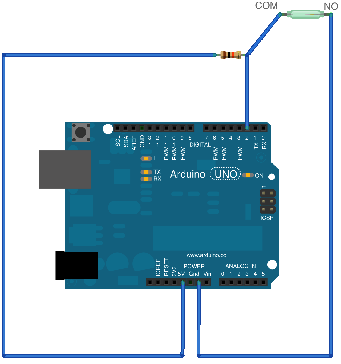
Diagram


Working & Arduino Sketch


The above circuit is very simple in fact it is just a continuity check in an arduino.The ground of the Arduino is connected to a Reed switch and +5V of Arduino is connected to the other end of the Arduino with a LOAD.LOAD is connected in order to prevent the frying of Arduino.Arduino would be jammed if its Vcc and gnd are connected . Now to check whether the circuit is close the line is tapped and is given to any of the I/O pins in Arduino.

Program

//The following sketch blinks a LED when a magnet is brought near the sensor.

setup()
{
  pinMode(13,OUTPUT);
  pinMode(2,INPUT);  //change the pin number based on IO pin you connect
}
void loop()
{
  int sensorinput=digitalRead(2);
  if(sensorinput==HIGH)
  {
    digitalWrite(13,HIGH);
  }
  else
  {
    digitalWrite(13,LOW);
  }
}


Reed switch as a Door Sensor

Place the reed switch on one side of the door and a magnet on other side of the door. When the door is open the Circuit is broken and when the door is closed the circuit is inturn closed.


Monday, 26 January 2015

8.ARDUINO BASED MOTION DETECTOR

PIR sensors are those which scans its environment and fixes its reference value.When there is any movement in the scanned region it sends out a analog signal.The analog signal is converted to a digital signal for convenience using a comparator and the digital signal is analysed using an Arduino.

DIAGRAM

PIR motion sensor connectivity with Arudino

Sketch

// THE FOLLOWING SKETCH BLINKS AN LED IF THERE IS A MOTION IN THE RANGE OF THE SENSOR

void setup()
{
  pinMode(2,INPUT);           //sensor input
  pinMode(13,OUTPUT);    // on board LED 
}
void loop()
{
  int sensorinput=digitalRead(2);
  if(sensorinput==HIGH)
  {
    digitalWrite(13,HIGH);
  }
  else
  {
    digitalWrite(13,LOW);
  }
}

PIR CALLIBRATION


You will notice two potentiometer  on the PIR sensors one would be to adjust the sensitivity of the sensor and other would be for the delay time of the sensor.

1st potentiometer is used for sensitivity ie it controles the scan ranging ratio for fixing the referance value.
2nd potentiometer is used for the time adjustment ie when the PIR is triggered with a motion it sends out an analog output ( digital output if the analog value is sent to an comparator) and waits for a particulat time for rescanning for the referance value again. Adjusting this would be to increase or decrease the delay time of the sensor.

Sunday, 25 January 2015

PID based line follower with L293D MOTOR DRIVER

1) 2 DC motors with required wheels
              -Its better to have a metal gear micro motors for higher speed But if not available you can use normal DC motors.
2)Arduino Micro-controllers
               --Arduino or a clone of it can be used.
3)L293D motor driver (or) any other motor driver to run two motors
4)Batteries
5)6 IR Sensors or a QTR-RC arrays
6)Connecting wires
7)control system-PID

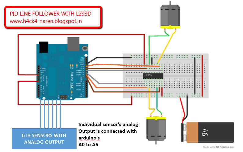
This is a line follower which implements PID to calculate its deviations from the line and act accordingly. This gives the robot with high speed and less oscillations.


·         The proportional value is approximately proportional to your robot’s position with respect to the line. That is, if your robot is precisely centered on the line, we expect a proportional value of exactly 0. If it is to the left of the line, the proportional term will be a positive number, and to the right of the line, it will be negative. This is computed from the result returned by read_line() simply by subtracting 2000.
·         The integral value records the history of your robot’s motion: it is a sum of all of the values of the proportional term that were recorded since the robot started running.
·         The derivative is the rate of change of the proportional value. We compute it in this example as the difference of the last two proportional values.


Diagram


Program

#include <QTRSensors.h>

#define Kp  0.5// experiment to determine this, start by something small that just makes your bot follow the line at a slow speed
#define Kd  2// experiment to determine this, slowly increase the speeds and adjust this value. ( Note: Kp < Kd) 

#define rightMaxSpeed 150 // max speed of the robot
#define leftMaxSpeed 150 // max speed of the robot

#define rightBaseSpeed 150 // this is the speed at which the motors should spin when the robot is perfectly on the line
#define leftBaseSpeed 150  // this is the speed at which the motors should spin when the robot is perfectly on the line


#define NUM_SENSORS  6     // number of sensors used
#define TIMEOUT       2500  // waits for 2500 us for sensor outputs to go low
#define EMITTER_PIN   2     // emitter is controlled by digital pin 2


#define rightMotor2 4
#define rightMotorPWM 5


#define leftMotor2 11
#define leftMotorPWM 10


QTRSensorsRC qtrrc((unsigned char[]) {A0,A1,A2,A3,A4,A5} ,NUM_SENSORS, TIMEOUT, EMITTER_PIN); //analog sensor connected through analog pins A0 - A5

unsigned int sensorValues[NUM_SENSORS];

void setup()
{
  Serial.begin(9600);
  Serial.print("start");
  pinMode(rightMotor2, OUTPUT);
  pinMode(rightMotorPWM, OUTPUT);
  
  pinMode(leftMotor2, OUTPUT);
  pinMode(leftMotorPWM, OUTPUT);
  
  
digitalWrite(13,HIGH); 
for (int i = 0; i < 300; i++) // calibrate for sometime by sliding the sensors across the line, or you may use auto-calibration instead
{
     qtrrc.calibrate();    
        
}    
digitalWrite(13,LOW);     
     
     
  // comment out for serial printing
    
    for (int i = 0; i < NUM_SENSORS; i++)
    {
      Serial.print(qtrrc.calibratedMinimumOn[i]);
      Serial.print(' ');
    }
    Serial.println();

    for (int i = 0; i < NUM_SENSORS; i++)
    {
      Serial.print(qtrrc.calibratedMaximumOn[i]);
      Serial.print(' ');
    }
    Serial.println();
    Serial.println();
    
  } 

int lastError = 0;

void loop()
{
  unsigned int sensors[6];
  
int position = qtrrc.readLine(sensors); // get calibrated readings along with the line position, refer to the QTR Sensors Arduino Library for more details on line position.
 
 int error = position - 2500;
 
Serial.println(position);   //returns the current position of the robot to calculate the error.

  int motorSpeed = Kp * error + Kd * (error - lastError);
  lastError = error;

  int rightMotorSpeed = rightBaseSpeed + motorSpeed;
  int leftMotorSpeed = leftBaseSpeed - motorSpeed;
  
 if (rightMotorSpeed > rightMaxSpeed ) 
       rightMotorSpeed = rightMaxSpeed; // prevent the motor from going beyond max speed
 if (leftMotorSpeed > leftMaxSpeed ) 
       leftMotorSpeed = leftMaxSpeed; // prevent the motor from going beyond max speed
 if (rightMotorSpeed < 0) 
       rightMotorSpeed = 0; // keep the motor speed positive
 if (leftMotorSpeed < 0) leftMotorSpeed = 0; // keep the motor speed positive
   {
  
  
  analogWrite(rightMotorPWM, rightMotorSpeed);
  digitalWrite(rightMotor2, LOW);

  
  analogWrite(leftMotorPWM, leftMotorSpeed);
  digitalWrite(leftMotor2, LOW);
 
}
}
void turn_left()
{
 digitalWrite(5,HIGH);
  digitalWrite(4,LOW);
}
void turn_right()
{
  digitalWrite(10,LOW);
  digitalWrite(11,HIGH);
}

Working

The Robot instantaneously checks the position of the robot and corrects accordingly. The robot is calibrated initially   by exposing all the 6 six sensors to the black line so that the robot judges the dark and light bands with respective to its thickness.
The robot makes a reference position of the line and the robot and if the robot deviates it calculates the error and multiplies with a constant Kp and Kd and the result is fed to the speed of the motors.

PID calibration

Kp and Kd must be found out only by expt. Initially keep the Kp value as .5 and increase it slowly in order to make the robot follow the line. However after the robot starts to follow the line the deviations can be reduced to .1% error by slowly increasing the Kd value till the robot goes without oscillations .