Sunday, 25 January 2015

PID based line follower with L293D MOTOR DRIVER

1) 2 DC motors with required wheels
              -Its better to have a metal gear micro motors for higher speed But if not available you can use normal DC motors.
2)Arduino Micro-controllers
               --Arduino or a clone of it can be used.
3)L293D motor driver (or) any other motor driver to run two motors
4)Batteries
5)6 IR Sensors or a QTR-RC arrays
6)Connecting wires
7)control system-PID

This is a line follower which implements PID to calculate its deviations from the line and act accordingly. This gives the robot with high speed and less oscillations.


·         The proportional value is approximately proportional to your robot’s position with respect to the line. That is, if your robot is precisely centered on the line, we expect a proportional value of exactly 0. If it is to the left of the line, the proportional term will be a positive number, and to the right of the line, it will be negative. This is computed from the result returned by read_line() simply by subtracting 2000.
·         The integral value records the history of your robot’s motion: it is a sum of all of the values of the proportional term that were recorded since the robot started running.
·         The derivative is the rate of change of the proportional value. We compute it in this example as the difference of the last two proportional values.


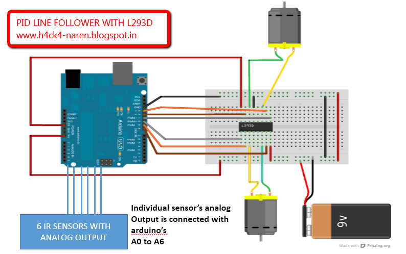
Diagram


Program

#include <QTRSensors.h>

#define Kp  0.5// experiment to determine this, start by something small that just makes your bot follow the line at a slow speed
#define Kd  2// experiment to determine this, slowly increase the speeds and adjust this value. ( Note: Kp < Kd) 

#define rightMaxSpeed 150 // max speed of the robot
#define leftMaxSpeed 150 // max speed of the robot

#define rightBaseSpeed 150 // this is the speed at which the motors should spin when the robot is perfectly on the line
#define leftBaseSpeed 150  // this is the speed at which the motors should spin when the robot is perfectly on the line


#define NUM_SENSORS  6     // number of sensors used
#define TIMEOUT       2500  // waits for 2500 us for sensor outputs to go low
#define EMITTER_PIN   2     // emitter is controlled by digital pin 2


#define rightMotor2 4
#define rightMotorPWM 5


#define leftMotor2 11
#define leftMotorPWM 10


QTRSensorsRC qtrrc((unsigned char[]) {A0,A1,A2,A3,A4,A5} ,NUM_SENSORS, TIMEOUT, EMITTER_PIN); //analog sensor connected through analog pins A0 - A5

unsigned int sensorValues[NUM_SENSORS];

void setup()
{
  Serial.begin(9600);
  Serial.print("start");
  pinMode(rightMotor2, OUTPUT);
  pinMode(rightMotorPWM, OUTPUT);
  
  pinMode(leftMotor2, OUTPUT);
  pinMode(leftMotorPWM, OUTPUT);
  
  
digitalWrite(13,HIGH); 
for (int i = 0; i < 300; i++) // calibrate for sometime by sliding the sensors across the line, or you may use auto-calibration instead
{
     qtrrc.calibrate();    
        
}    
digitalWrite(13,LOW);     
     
     
  // comment out for serial printing
    
    for (int i = 0; i < NUM_SENSORS; i++)
    {
      Serial.print(qtrrc.calibratedMinimumOn[i]);
      Serial.print(' ');
    }
    Serial.println();

    for (int i = 0; i < NUM_SENSORS; i++)
    {
      Serial.print(qtrrc.calibratedMaximumOn[i]);
      Serial.print(' ');
    }
    Serial.println();
    Serial.println();
    
  } 

int lastError = 0;

void loop()
{
  unsigned int sensors[6];
  
int position = qtrrc.readLine(sensors); // get calibrated readings along with the line position, refer to the QTR Sensors Arduino Library for more details on line position.
 
 int error = position - 2500;
 
Serial.println(position);   //returns the current position of the robot to calculate the error.

  int motorSpeed = Kp * error + Kd * (error - lastError);
  lastError = error;

  int rightMotorSpeed = rightBaseSpeed + motorSpeed;
  int leftMotorSpeed = leftBaseSpeed - motorSpeed;
  
 if (rightMotorSpeed > rightMaxSpeed ) 
       rightMotorSpeed = rightMaxSpeed; // prevent the motor from going beyond max speed
 if (leftMotorSpeed > leftMaxSpeed ) 
       leftMotorSpeed = leftMaxSpeed; // prevent the motor from going beyond max speed
 if (rightMotorSpeed < 0) 
       rightMotorSpeed = 0; // keep the motor speed positive
 if (leftMotorSpeed < 0) leftMotorSpeed = 0; // keep the motor speed positive
   {
  
  
  analogWrite(rightMotorPWM, rightMotorSpeed);
  digitalWrite(rightMotor2, LOW);

  
  analogWrite(leftMotorPWM, leftMotorSpeed);
  digitalWrite(leftMotor2, LOW);
 
}
}
void turn_left()
{
 digitalWrite(5,HIGH);
  digitalWrite(4,LOW);
}
void turn_right()
{
  digitalWrite(10,LOW);
  digitalWrite(11,HIGH);
}

Working

The Robot instantaneously checks the position of the robot and corrects accordingly. The robot is calibrated initially   by exposing all the 6 six sensors to the black line so that the robot judges the dark and light bands with respective to its thickness.
The robot makes a reference position of the line and the robot and if the robot deviates it calculates the error and multiplies with a constant Kp and Kd and the result is fed to the speed of the motors.

PID calibration

Kp and Kd must be found out only by expt. Initially keep the Kp value as .5 and increase it slowly in order to make the robot follow the line. However after the robot starts to follow the line the deviations can be reduced to .1% error by slowly increasing the Kd value till the robot goes without oscillations .
#WEEK 1 :SIMPLE PROJECT ON HOW TO MAKE A AUTOMATIC EVENING LAMP WITH ARDUINO FOR YOUR HOUSE


Total cost and Materials

 LDR                               -  35 Rs max.
An Arduino UNO           -  1300 Rs.
(or)
An Arduino clone           - 500 Min and 900 Max.
1Amp 5v input relay               -50 MAX.
230 v lamp                       - Depends on type of lamp you use.

Total Min cost :Rs 585

Working

Aim

To make a lamp which can detect the external light and turn off automatically and turns on when there is no external light.

Diagram


Program

boolean flag;  //CHECKS WHETHER THE LIGHT IS ON OR OFF.
void setup()
{
  pinMode(8,OUTPUT);  // connected to the Trigger of the Relay
  pinMode(A0,INPUT);  //To read the sensor Readings
  Serial.begin(9600); //Start serial monitor to troubleshoot during the project
}
void loop()
{
  int sensorinput;
  sensorinput=analogRead(A0); //Reads the value of the sensor
  Serial.println(sensorinput);
  
  // NOW CHECK THE READING OF THE SENSOR BY EXPOSING IT TO BRIGHT LIGHT AND DARK ATMOSPHERE
  // TO KNOW THE THRESHOLD VALUE OF THE LIGHT FOR EXAMPLE WHEN THE SENSOR RECEIVES A BRIGHT LIGHT IT GIVES A MAX VALUE ASSUME IT TO BE 500 AND IN DARK CONDITIONS IT GIVES 0.AS THE LIGHT GETS DIMMER TO THE SENSOR THE READINGS DECREASE FROM 500
  // CHECK THE MAX VALUE OF THE SENSOR AND MAKE A TRIAL AND ERROR AND FIND THE THRESHOLD FOR WHICH THE LAMP HAS TO TURN ON .
  // I HAVE TAKEN 200 FOR THE POST
  
  int threshold=200;
  if(sensorinput<threshold)         //LESS ENVIRONMENT LIGHT
  {
    Serial.println("LIGHTS ON");
    flag=true;
    pinMode(8,HIGH);
  }
  else
  {
    Serial.println("LIGHTS OFF");
    flag=false;
    pinMode(8,LOW);
  }
}

WORKING

In order to understand this project you need to know what is a Relay.

What is a relay?  (FROM http://www.circuitstoday.com/working-of-relays)

We know that most of the high end industrial application devices have relays for their effective working. Relays are simple switches which are operated both electrically and mechanically. Relays consist of a n electromagnet and also a set of contacts. The switching mechanism is carried out with the help of the electromagnet. There are also other operating principles for its working. But they differ according to their applications. Most of the devices have the application of relays.

Why is a relay used?

The main operation of a relay comes in places where only a low-power signal can be used to control a circuit. It is also used in places where only one signal can be used to control a lot of circuits. The application of relays started during the invention of telephones. They played an important role in switching calls in telephone exchanges. They were also used in long distance telegraphy. They were used to switch the signal coming from one source to another destination. After the invention of computers they were also used to perform Boolean and other logical operations. The high end applications of relays require high power to be driven by electric motors and so on. Such relays are called contacts.
Relay generally has 5 terminals . NORMALLY CLOSED,NORMALLY OPEN,COMMON,GROUND,TRIGGER.
IN THE ABOVE DIAGRAM LIVE WIRE OF THE SOCKET IS CONNECTED TO A LAMP AND THE NEUTRAL CONNECTION OF THE LAMP COMES FROM THE Relay's NORMALLY OPEN.WHEN A TRIGGER OF 5V IS SUPPLIED TO THE COIL OF THE RELAY (SAY SENSOR RETURNS A VALUE LESS THAN 200 ).THE COIL MAGNETISES AND THE COMMON GETS CONNECTED TO NORMALLY OPEN INTERNALLY. NOW THE LAMP HAS A CLOSED CIRCUIT AND LIGHT GLOWS AGAIN WHEN THERE IS A HIGH RESPONSE FROM THE SENSOR AND PIN 8 ON ARDUINO GOES LOW  AND THE COIL OF THE RELAY DE-MAGNETISES AND THE CIRCUIT FOR THE LAMP IS BROKEN  AND HENCE THE LIGHT GOES OFF.
LOGIC

SENSOR STATE
ARDUINO DIGITAL PIN STATE
RELAY STATE
LIGHT STATE
threshold> 200
Else part executes
Digital pin goes LOW
Breaks the lamp’s circuit
OFF
<200
If part executes digital pin goes HIGH
Closes the lamp’s circuit
ON


7. Serial communication from a computer or external device from an Arduino


PC to Arduino communication


This post describes on how a PC or any other wireless or wired device is going to send a message to a Arduino.This will explain a serial communication of a PC-Arduino & a Bluetooth-Arduino.


PC communication with a Arduino (Receiving serial data in Arduino)

It is easy to receive 8-bit values ,because at Serial functions use 8 bit values.The following sketch receives a digit from the computer and blinks the LED based on the number which is pressed on the computer's keyboard.


int ledpin=13;
int blinkRate=0;

void setup()
{
  Serial.begin(9600);   //STARTS THE SERIAL COMMUNICATION
  pinMode(13,OUTPUT);   //ACTIVATES THE ONBOARD LED
}
void loop()
{
  if(Serial.available())
  {
    char ch=Serial.read();
    if(isDigit(ch))   //if it is a number bw 0 to 9 (checks the ascii value
    {
      blinkRate(ch-'0');  //entered number's ASCII value is converted to number
      blinkRate=blinkRate*100;
    }
    digitalWrite(13,HIGH);
    delay(blinkRate);
    digitalWrite(13,LOW);
    delay(blinkRate);
  }
}
      

Descriptoin

The above sketch gets an input from the serial communication and converts it to no of seconds to blink.

Step 1:  check whether Serial connection is avail by Serial.available().
Step 2:  Read the input .
Step 3: The read input will be in ASCII so convert it to numeric value.
Step 4: Convert the numeric value to seconds to notice the blink( if we dont convert then the blinks will be soo fast that it wont be visible with our eyes instead we need a high frame rate camera to see it).
Step 5:Use the blink sketch and blink the LED with respect to the BlinkRate of number.