Thursday, 5 February 2015

Controlling a Servo motor.!!


Servo motor is a DC motor where its rotary motion can be controlled based on the signal voltage we supply to it. Servo motor uses PWM where varying the signal gives different angles on its arm.

A typical servo motor consist of three wires namely Vcc,Ground,Signal where Vcc and ground will be hooked up for powering the motor.

Note:
A servo may malfunction if it is not supplied with enough power source .For example if your Arduino is plugged in with your Computer's USB jack then there is a possibility that the USB cannot deliver the required current to the motor.Connecting a separate battery (5v)will solve this issue.
(malfunction can be :  1) No rotations  2) Servo doesnt obey the instructions delivered to it by Arduino 3) The arm of a 180 degree doesn't come back to original position once it has reached 180 degrees etc..)

There are two types of servos 
                          
1)180 degrees motion (0-5v delivers rotations based on 180 degrees)
2)360 degrees motion (0-5v delivers rotations based on 360 degrees)

Sketch (Example program for Arduino servo library)

#include <Servo.h> 
 
Servo myservo;  // create servo object to control a servo 
 Servo myservo1                           // a maximum of eight servo objects can be created 
 
int pos = 0;    // variable to store the servo position 
 
void setup() 
  myservo.attach(4);  // attaches the servo on pin 4 to the servo object 
  myservo1.attach(5);
//  myservo.write(pos); //edit the pos value to have a const turn
 
 
void loop() 
  for(pos = 0; pos < 180; pos += 1)  // goes from 0 degrees to 180 degrees 
  {                                  // in steps of 1 degree 
    myservo.write(pos);              // tell servo to go to position in variable 'pos' 
    delay(15);                       // waits 15ms for the servo to reach the position 
  } 
//for a 180 degree servo once it has reached 180 degree the servo automatically goes back to 0 pos
  for(pos = 0; pos>=180; pos++)     // goes from 180 degrees to 0 degrees 
  {                                
    myservo1.write(pos);              // tell servo to go to position in variable 'pos' 
    delay(15);                       // waits 15ms for the servo to reach the position 
  } 


Working of the Sketch

Two servo motor signal wires are wired to pin 4 and 5 of the Arduino and a command is given to the motor to move its arm from 0 to 180 degree on both the servo .Servos are differentiated based on the objects for the class servo.

so based on the position we provide the servo changes its angle.so the loop sweeps the angle from 0 to 180 and once the servo reaches 180 it again reaches back to initial state and again runes the code,

you want to make a turn to particular angle use the code

myservo.write(39);
Wednesday, 4 February 2015

Control your Robot using your Android mobile using a Bluetooth

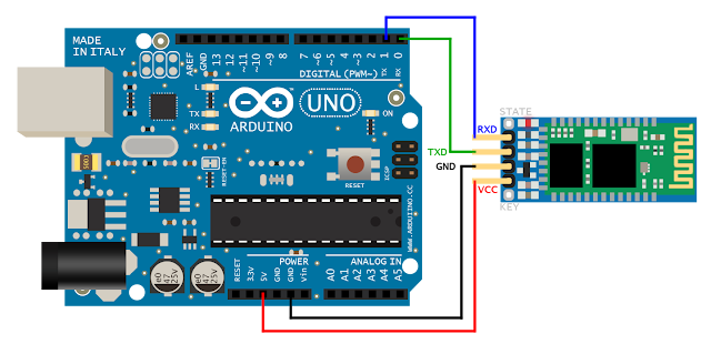
Controlling a Arduino with an android is very easy.Since Arduino communicates with other device using a serial interface we need to sort out how we are going to connect our Android to our Arduino.

Materials Used

A Android Mobile
Arduino
Bluetooth Module
Testing LED or any other Actuators
Few connecting wires


Connections


Sketch
//The following sketch blinks an LED when you send a message from your mobile
//Any other control other than a LED can also be made by editing the required block of LED in the sketch

void setup()
{
  pinMode(13,OUTPUT);
  Serial.begin(9600); // very important since BTmodule is going to communicate with arduino with serial communication
}
void loop()
{
  if(Serial.available()>0)
  {
    int input=Serial.read();
    if(input=='a')
      digitalWrite(13,HIGH);
      delay(3000); // to notice the blink of LED
    else
      digitalWrite(13,LOW);
  }
}


Configure your Android

1) Go to Playstore
2)Download the existing app SENA Bterm Bluetooth Terminal
3)connect the app with your Arduino BT module
4)Now its time to control
5) Inside the APP go to Terminal and send the character 'a' and you can see a LED blink on the Arduino
6)DONE make your own robot with it..!!

Monday, 2 February 2015

Arduino based House Security system


Making a Arduino based house security system is very easy.The above schematic shows how to work on PIR sensors,door sensors,vibration sensors and trigger a buzzer for emergency.The above model can be enhanced by adding GSM module to give a call to your mobile or check your security cameras on your mobile remotely.
Several advancement in house automation will be shared on blog as per the portions on Arduino based on difficulty level. 

Working

The working of the above connections with the Arduino is very simple. Arduino gets a input from the sensor as digital signal and triggers the alarm when the burglar system is active.
placement of various sensor must be the factor responsible for better enhancement of security. Door sensor must be placed on one side of the door and the magnet has to be fixed on the other closing end in such a way that the opening of the door must trigger the Arduino.

Motion sensor cannot detect the movement if a glass is placed in its sensing area so if you want to reduce the extent of detection to a certain area glass can be used for a cover.

vibration sensors can be used on your safe so that tampering the safe or locker would trigger the Arduino and a alarm is striked.

Program   //code is not tested but soon after a test vid will be posted

int vibrationsensor=4;
int motionsensor=8;
int doorsensor=5;
int buzzer=12;
int button=3;
boolean state=true; // To check the state whether the burgler alarm is ON or off
void setup()
{
  pinMode(vibrationsensor,INPUT);
  pinMode(motionsensor,INPUT);
  pinMode(dooorsensor,OUTPUT);
  pinMode(buzzer,OUTPUT);
  pinMode(button,INPUT);        // connect a switch or a button to the 3rd pin with a resistor connected in series and the other end to ground
  Serial.begin(9600);
}
void loop()
{
  
  int buttonread=digitalRead(button);
  if((buttonread==HIGH)&&(state==TRUE))
  {
  Serial.println("SYSTEM ON");
  int vibration=digitalRead(vibrationsensor);
  int motiondet=digitalRead(motionsensor);
  int doorsen=digitalRead(doorsensor);
  
  if((vibration==HIGH)||(motiondet==HIGH)||(doorsen==HIGH))
  {
    buzzer();
  }
  else'
  {
    if(buttonread==HIGH)
    {
      if(state==false)
      {
        state=true;
      }
      else
      {
        state=false;
      }
  }
  }
  void buzzer()
  { 
  digitalWrite(12,HIGH);
  delay(2000);
  buttonread=digitalRead(button);
  id(buttonread==HIGH)
  {
    state=true;
  }
  else
  {
    state=false;
  }
  }
  

enhancements

A charging circuit has to be added to Arduino with a inbuilt batteries to safe guard its running during power failures.

All wired connections can be made wireless.

Full module can be added with the house automation for better result.

Using of networks could make easier for the user to control the device.


Thursday, 29 January 2015

11)Detecting the Distance using a Ultra-Sonic sensor


Ultrasonic sensors works similar to a radar which gets the presence of  target by interpreting the echoes from radio or sound waves . Active ultrasonic sensors generate high frequency sound waves and detects the echo which is received back by the sensor and then measures the time interval between sending resumption of  the echo to determine the distance to an object.

Working


The working of Ultrasonic sensor is just based on how the bat flies, It sends out a ultrasonic wave and waits for its echo to return back if it returns back then it takes a either turn or it continues path.

Now mathematically we define speed = (distance) / (Time);

So this would imply distance=speed * Time;

Parameters known

1)speed of ultrasonic sensor.
2)Time taken for it to strkte an object and echo.  ie  (observed Time /2 ) will be the time to strike the object and return to its original origin.
3)Distance can be found by the desired form.

check the following site to know the speed of ultrasonic sensor in various medium http://www.classltd.com/sound_velocity_table.html

Diagram


Pins on a US sensor

                              1) Vcc
                              2)Gnd
                              3)Trigger ( provide Vcc to send a ultrasonic signal)
                              4)echo      (Rx)


Sketch

//The following program prints the distance in the serial monitor and blinks an LED when distance is less than 10Meters

#define trigger 2
#define echo 3
void setup()
{
   pinMode(trigger,OUTPUT);
   pinMode(echo,INPUT);
   pinMode(13,OUTPUT);
   Serial.begin(9600);
}
void loop()
{
   int time,distance;
   
// Now send out a ultrasonic wave for one second

digitalWrite(trigger,HIGH);
delay(1000); // transmitting a wave for 1 second
digitalWrite(trigger,LOW);

time=pulseIn(echo,HIGH);  // Returns the length of pulse in Micro-seconds  check http://arduino.cc/en/Reference/pulseIn for more info
distance=(time/2)/29.1;        //

Serial.println(distance);

if(distance<10)
{
   digitalWrite(13,HIGH);
}
else
{
  digitalWrite(13,LOW);
}
}


Wednesday, 28 January 2015

10 . Using vibration sensor in Ardunio


How much ever secure we keep our house there always exist some vulnerability to break into.This post explains how to use a vibration sensor with use of Arduino.
The Sensor detects any type of vibrations and returns Vcc as output. Its interface to Arduino is very simple in a way that the output of the sensor is fed to any of the I/O pins of the Arduino and is stored in some variable. If the IO pin of the Arduino returns a HIGH then there is a vibration on the sensor else the state of arduino will be in monitoring mode.

Calibration

There is a small potentiometer on the sensor which measures the depth of vibration to detect and act accordingly.Based on the value of the potentiometer the sensitivity of the sensor decreases or increases.


Diagram:


Program

// The following program blinks an LED when the sensor detects vibration
void setup()
{
   pinMode(3,INPUT);
   pinMode(13,OUTPUT);
}
void loop()
{
  int sensorinput=digitalRead(3);
  if (sensorinput==HIGH)
  {
            digialWrite(13,HIGH);
  }
  else
  {
           digitalWrite(13,LOW);
 }
}

Tuesday, 27 January 2015

DOOR SENSORS WITH ARDUINO


Using door sensors are very basic prerequisites in electronics. Door sensors are just a Reed Switch where the Switch gets activated when subjected to electromagnetic waves.When in normal condition it gets deactivated.


Both single and dual contact reed switch is very simple . In single contact switch only one connection can be made while in dual contact is just an exact replica of a Relay which i have explained in your session on "HOW TO MAKE A AUTOMATIC EVENING LAMP".

Diagram


Working & Arduino Sketch


The above circuit is very simple in fact it is just a continuity check in an arduino.The ground of the Arduino is connected to a Reed switch and +5V of Arduino is connected to the other end of the Arduino with a LOAD.LOAD is connected in order to prevent the frying of Arduino.Arduino would be jammed if its Vcc and gnd are connected . Now to check whether the circuit is close the line is tapped and is given to any of the I/O pins in Arduino.

Program

//The following sketch blinks a LED when a magnet is brought near the sensor.

setup()
{
  pinMode(13,OUTPUT);
  pinMode(2,INPUT);  //change the pin number based on IO pin you connect
}
void loop()
{
  int sensorinput=digitalRead(2);
  if(sensorinput==HIGH)
  {
    digitalWrite(13,HIGH);
  }
  else
  {
    digitalWrite(13,LOW);
  }
}


Reed switch as a Door Sensor

Place the reed switch on one side of the door and a magnet on other side of the door. When the door is open the Circuit is broken and when the door is closed the circuit is inturn closed.